The Logic Circuit Shown Below Has The Input Waveforms ‘a And ‘b
The Logic Circuit Shown Below Has The Input Waveforms ‘a And ‘b
If this picture is your intelectual property (copyright infringement) or child pornography / immature images, please Contact Us for abuse. We will follow up your report/abuse within 24 hours.
Related Images of solved 1 which output waveform is correct for the circuit
Solved 1 Which Output Waveform Is Correct For The Circuit
Solved 1 Which Output Waveform Is Correct For The Circuit

Solved What Is The Correct Output Waveform For The Circuit Given In The Course Hero
Solved What Is The Correct Output Waveform For The Circuit Given In The Course Hero

Solved 1 Which Output Waveform Is Correct For The Cir
Solved 1 Which Output Waveform Is Correct For The Cir

Solved What Is The Correct Output Waveform For The Circuit Given In The Course Hero
Solved What Is The Correct Output Waveform For The Circuit Given In The Course Hero
Solved Which Output Waveform Is Correct For The Circuit
Solved Which Output Waveform Is Correct For The Circuit

Solved Which Output Waveform Is Correct For The Circuit
Solved Which Output Waveform Is Correct For The Circuit

Solved 1 Which Output Waveform Is Correct For The Cir
Solved 1 Which Output Waveform Is Correct For The Cir
Solved Select The Correct Output Waveform For The Circuit
Solved Select The Correct Output Waveform For The Circuit
Solved Question 1 Select The Correct Output Waveform For The
Solved Question 1 Select The Correct Output Waveform For The
Solved Question 1 Select The Correct Output Waveform For The
Solved Question 1 Select The Correct Output Waveform For The

Solved 1 Which Output Waveform Is Correct For The Cir
Solved 1 Which Output Waveform Is Correct For The Cir

Solve Fast 1 Determine The Output Waveform For The Following Course Hero
Solve Fast 1 Determine The Output Waveform For The Following Course Hero
Solved Question 1 Select The Correct Output Waveform For The
Solved Question 1 Select The Correct Output Waveform For The

Solved Describe The Output Waveform Of Each Circuit In
Solved Describe The Output Waveform Of Each Circuit In

Solved Question 1 Determine The Output Waveform And Calculate The Output Dc Level And The
Solved Question 1 Determine The Output Waveform And Calculate The Output Dc Level And The

Solved 1 Which Output Waveform Is Correct For The Cir
Solved 1 Which Output Waveform Is Correct For The Cir


In Circuit Shown In Figure Determine The Output Waveform Output Dc
In Circuit Shown In Figure Determine The Output Waveform Output Dc
Solved Choose The Correct Output Waveform Of The Given
Solved Choose The Correct Output Waveform Of The Given

Solved Q1 Draw The Output Waveform For The Following
Solved Q1 Draw The Output Waveform For The Following


The Logic Circuit Shown Below Has The Input Waveforms ‘a And ‘b
The Logic Circuit Shown Below Has The Input Waveforms ‘a And ‘b

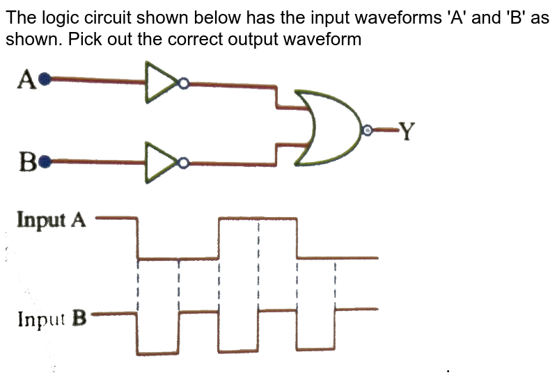
The Logic Circuit Shown Below Has The Input Waveforms A And B As Shown Pick Out The Correct
The Logic Circuit Shown Below Has The Input Waveforms A And B As Shown Pick Out The Correct

The Logic Circuit Shown Below Has The Input Waveforms A And B As Shown Pick Out The Correct
The Logic Circuit Shown Below Has The Input Waveforms A And B As Shown Pick Out The Correct

The Logic Circuit Shown Below Has The Input Waveforms ‘a And ‘b As Shown Pick Out The Correct
The Logic Circuit Shown Below Has The Input Waveforms ‘a And ‘b As Shown Pick Out The Correct
Solved Question 1 Select The Correct Output Waveform For The
Solved Question 1 Select The Correct Output Waveform For The
Solved Draw Below The Output Waveform For The Circuit In
Solved Draw Below The Output Waveform For The Circuit In

The Output Waveform Of The Given Logical Circuit For The Following Inputs
The Output Waveform Of The Given Logical Circuit For The Following Inputs

Solved Figure 2a Depicts The Schematic Diagram Of An Ideal Op Amp Differentiator Circuit
Solved Figure 2a Depicts The Schematic Diagram Of An Ideal Op Amp Differentiator Circuit

Question Waveforms A And B As Shown Pick Out The Correct Output Waveform
Question Waveforms A And B As Shown Pick Out The Correct Output Waveform
Solved Question 1 Select The Correct Output Waveform For The
Solved Question 1 Select The Correct Output Waveform For The
5 Draw The Output Waveform Of The Circuit Shown In Fi
5 Draw The Output Waveform Of The Circuit Shown In Fi

Draw The Output Waveform Across The Resistor Figure
Draw The Output Waveform Across The Resistor Figure

Solved Select The Correct Graph For The Output Waveform For
Solved Select The Correct Graph For The Output Waveform For

Solved 10 In The Given Circuit Draw The Output Waveform
Solved 10 In The Given Circuit Draw The Output Waveform
